Contents
As devices get more compact and with continual pressure on improving performance, there is a growing need to pack more energy in an electrical/electronic system and extract more when required. Battery packs are feeling the pinch. The space allowance is shrinking while performance requirements are increasing. This is all the more reason for Battery Thermal Management System to be engineered to perfection.
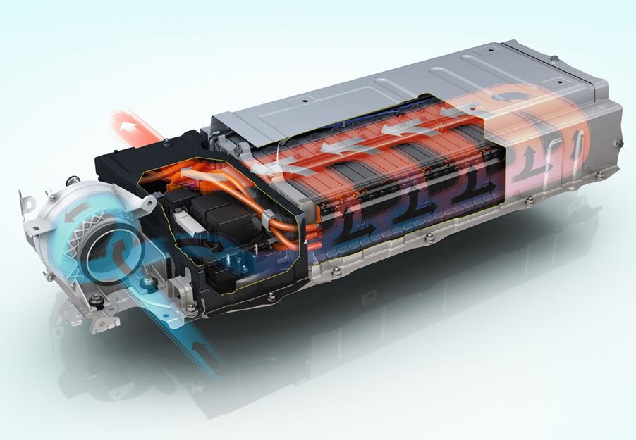
An Air Cooler Battery Thermal Management System (Prius) Courtesy: Toyota
In Electric Vehicles there is a pressing need to overcome the range anxiety and deliver cars capable of doing at least 100 miles per charge. Similarly, in hybrid cars, the electric drive is expected to match the performance of much larger I.C engine with a relatively small battery pack. Both the charging and discharging of electrochemical batteries causes heat to generate because of Joule heating and internal electrochemical processes. The small battery pack in a hybrid cars is one example of extreme application. The rate at which heat can be dissipated from such packs often limits the performance and functionality of the car.
In the battery industry, the term “C” is used a measure of discharge/charge rate. 1 C is equivalent to the current furnished by/to the battery to completely discharge/charge it in one hour. For a hybrid car, repetitive loads of 25 C during acceleration (discharge) and 10 C (charge) during regenerative braking are typical. These are similar loads as experienced by a pure Electric Vehicle but in a hybrid car, battery space is much more limited.
Expectations from a BTMS?
The build-up of heat in the batteries not only deteriorates their performance and life but can also result in thermal runaway. The phenomena of thermal runway can lead to not only battery failure but destruction (through explosion and fire). Failure of one cell, particularly those in connected in series can lead to failure of the whole pack.
Unless batteries are kept within the optimum operational limits, their performance will decay. For most batteries the temperatures should be kept within 5 °C to 30 °C range if possible. In addition, the BTMS should be designed such that the temperature difference between the cells in the pack should be kept within 5 °C. Having a few batteries cooler than the others decays the performance of the pack.
Thermal Analysis of Battery Pack
As specified by USABC, the life of the modern electric car battery should be at least 8-10 years. The battery life is curtailed if its temperature reaches above 40°C, even if it’s because of ambient temperature rather than loading. Likewise, extremely cold climates (sub zero temperatures) can also limit the amount of current that can be drawn from the battery. A hi- spec battery thermal management system therefore will actively try to ensure that these limits are not reached even if the vehicle is idle.
To recap, a well designed Battery Thermal Management System should
- Prevent Thermal Runaway
- Maintain temperature within 5 °C to 30°C
- Maintain a maximum of 5 °C degree temperature differential between any two cells in the pack
Types of BTMS
There are a number of ways in which cooling for a battery pack can be done. They can be broadly classified into active and passive systems. Passive cooling system rely on dissipating heat through natural convection and radiation. They have no moving parts and can be adequate if larger space envelope is available (relative to the size of battery) or low performance ( low charge/discharge rates) is required. Passive cooling systems often rely on increasing thermal inertia of the system by adding more thermal mass. Active cooling systems on the other hand rely on cooling fluid that is forced through the battery by means of a blower or positive displacement pump. The cooling fluid can be air or liquid.
Electric Vehicles present in the market today employ both air cooling and liquid cooling. Some examples of air cooled electric vehicles are Nissan Leaf, Mitsubishi I-MiEV, VW e-Golf and Toyota Prius. The liquid cooled electric vehicles include Tesla ( Sportster, Model S, Model X, Model 3), GM Volt and Porsche Panamera. It can be noticed that relatively higher performance electric cars opt for liquid cooling as the high heat capacity of a liquid allows much more control over heat dissipation. However pushing a possibly conducting liquid through an electric environment is extremely hazardous and provision has to be made to isolate the two. This almost always ensures that liquid cooling system is more costlier than air cooled counterpart.
Head wind as the vehicle moves can also be utilized for aiding cooling but on its own it is not sufficient. It should be noted that to prevent the battery from the elements (dust, debris and moisture) and for safety purposes (prevent nail penetration), the battery pack is shielded in layers of protective casing. This prevents the head wind to be used effectively for cooling.
Liquid Cooled BTMS
Within the liquid cooled BTMS, three different approaches have been adopted by the industry for cooling.
Cooling Fins
The idea of cooling fin is dissipate heat from the wide face of the cell where most heat is available for dissipation. A single cooling Fin is positioned between two cells. The thin cooling fin has a series of channels running through it. The cooling fins snap fits into position in between cooling blocks.
Cooling Fin for Chevy Volt
This cooling method is ideal as is consumes for both pouch and rectangular prismatic cells. It consumes small space and provides cooling directly to at least one face of the cell (depending upon the configuration). It has though a few disadvantages. Fins are costly to design and secondly there are several interfaces for cooling channels that can cause a leak unless adequate sealing measures are taken. Chevy Volt uses this type of cooling system developed by DANA.
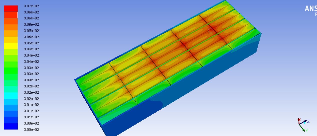
Cooling Matrix
This idea is normally employed for cylindrical cells. A hollow cooling shell is made with holes for containing the cells. Cooling liquid enters one end of the jacket and is made to exit at the diagonal end. The cooling matrix system is robust and helps maintain temperature limits by surrounding the cell with large thermal mass. The cooling jackets are normally welded leaving just the spigots at the end where sealing requirements have to be considered.
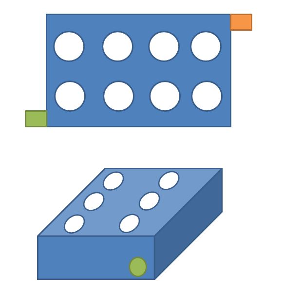
Cooling Matrix for cylindrical cells schematic
The disadvantage of this system is that it requires space and lowers the pack energy density. It also adds weight not only for the amount of metal in the jacket but also for the liquid body. In a small high performance battery pack, this system is ideal.
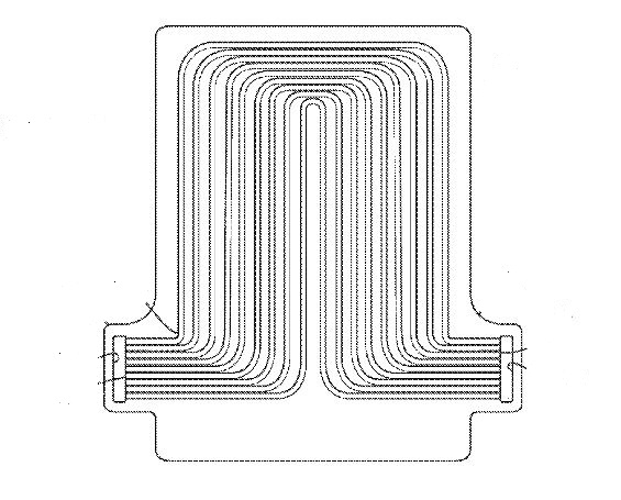
Cooling Plate
A cold plate with either serpentine or concentric channels running through it is another method by which heat can be efficiently dissipated. Cooling plates are one of the most cost effective solution for liquid cooling. Pre-fabricated cold plates are easily available from various suppliers. However, there are two major drawbacks of this system. Firstly cold plates to tend to add extra weight to the pack. Secondly they are mostly deployed underneath the cells. It should be noted that cells are much hotter near the tabs at the top because of higher current density. Thus cooling from the underside of the cells is not the most effective way of heat dissipation. This is specially true for pouch cells which have very small width.
Heat pipes with Phase Change
Heat pipes are an extremely efficient way of transporting heat passively. Heat pipes make use of both the principals of efficient heat transfer and phase change to shift the heat away from the source. Heat pipe is a closed loop pipe with two major segments namely the evaporator and the condenser. The heat generation area is attached with the evaporator section of the heat-pipe. There are a variety of phase change substances that can be used inside the pipe such as paraffin waxes. The selection of PCM (Phase change material) will depend upon the application. The paraffin wax used in its normal state (unheated state) is semi viscous solids. Once they absorb heat, they convert into liquid. This liquid than goes through the heat pipe loop because of capillary action or gravity. The PCM material than loses the heat in the condenser section located for away from the battery.
In the picture (right), an application of heat pipe in a cell-phone has been shown. The thermal image is also present. PCM pouches and plastic pack are also available in the market that can be placed right next to the battery surface for cooling in hot climates. Also interesting to note that they can be used also for heating in extreme cold conditions.
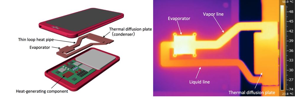
Heat Pipe used in phone along with thermal image (Courtesy Fujitsu)
Tesla’s Rectangular Cooling Tube
Tesla were one of the first to announce a high performance sports car with the release of Tesla Roadster. High performance requirement meant their cooling system also had to be top notch. Tesla has come up with a unique method to cool their thousands of 18650 cylindrical cells located in the bespoke chassis.
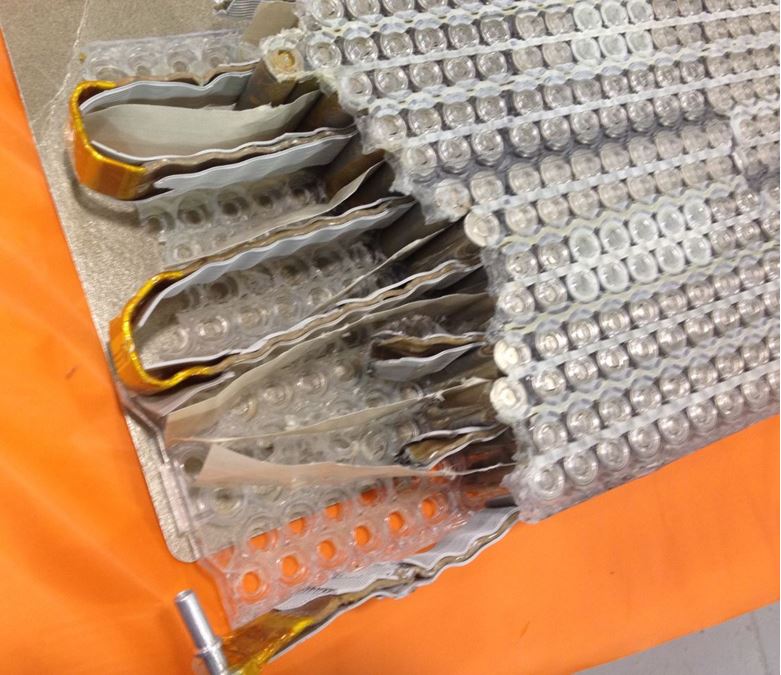
Tesla’s unique cooling system
This flexible tube provides direct cooling by maintaining contact with surface of every cell. As can be seen from the picture a thin layer of polymer material also separates the cooling tube from the battery.
Air Cooled BTMS
Generally air cooled systems are employed for application that are not heavy duty or extreme performance. Air cooled BTMS are low cost and uncomplicated compared to liquid cooled counterpart. The drawback of air cooled system is that its difficult to maintain even temperature across the pack. Air cooled systems can be identified by blowers and air filters connected to the battery pack. The following arrangements are popular in the industry:
Baffle Configuration
Baffle configuration is the simplest of all cooling systems. Air is blown by a fan over batteries lumped together. The air is not confined to channels within the battery pack. It is directed to different parts of the parts of the pack through baffles. The major disadvantage of this configuration is that other than changing air speed of the fan there is little control over heat dissipation.
Channel Configuration
Air is directed to different corners of battery pack using different channels. Techniques similar to HVAC ducting are used for regulating the speed and volume flow rate of air in different parts of the pack. It is difficult to balance air flow in the channel as it is limited to certain inlet speed of air. Channels can also increase space usage which in turn increases the volume of battery pack.
This link provides an insight on the Tesla’s unique battery thermal management system.
Please feel free to share this article using the buttons below